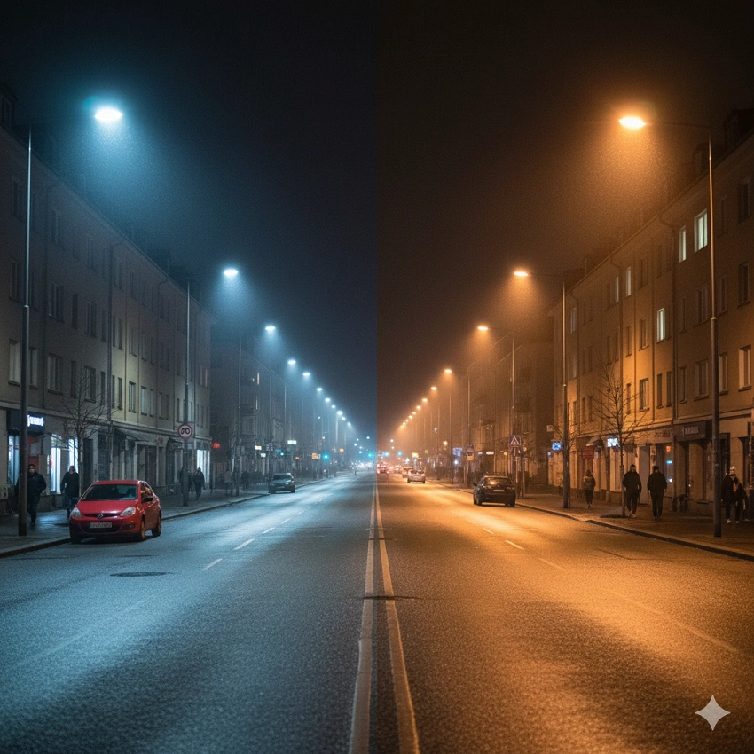
Select LED street lights for highways and local roads by matching the required lighting class to the road width, pole spacing, mounting height and luminaire distribution. Local roads often need less light output than wide highways, but wattage alone cannot establish suitable visibility or uniformity. To reduce dark zones between poles, correct the optical pattern and mounting geometry rather than simply choosing a higher-wattage fixture.
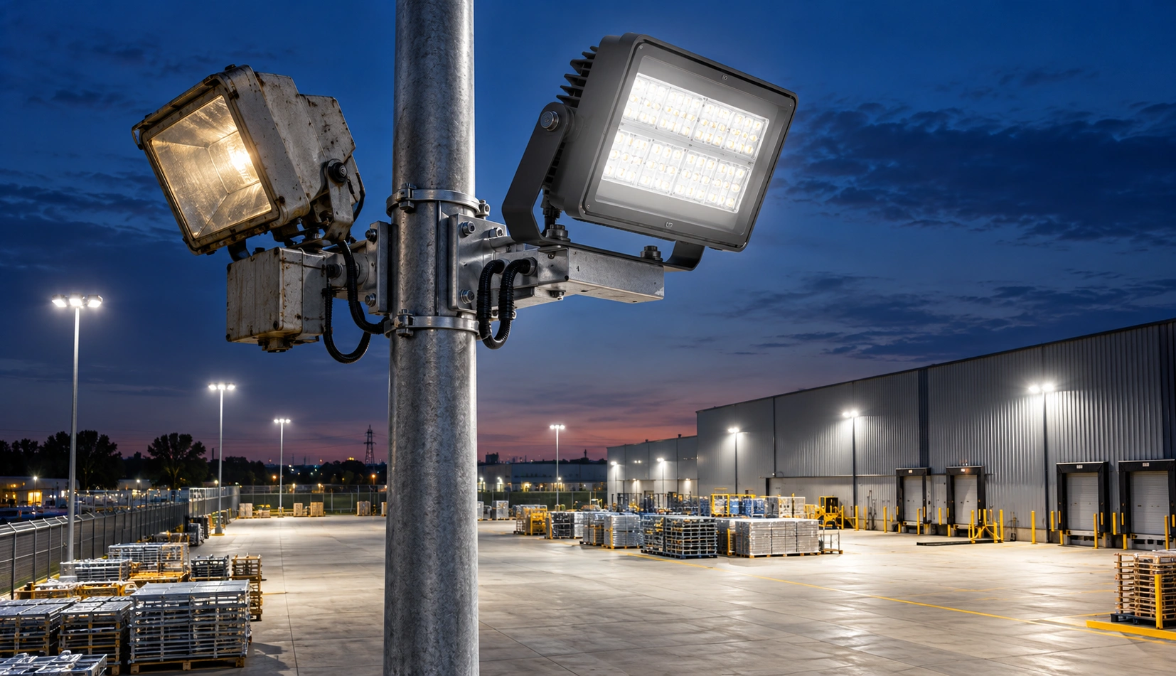
When replacing high-pressure sodium (HPS), metal-halide or ageing LED fixtures, first establish the road’s lighting targets and the existing system’s weak points. A useful replacement specification must explain not only which luminaires to buy, but also how the installation will perform on the road and how the completed work will be checked.
What Wattage Is Suitable for Highways and Local Roads?
As an initial screening guide, narrow local roads may call for 20-60W LED street lights, urban or collector roads 50-120W, arterial roads 80-180W, and highways 150-300W or other higher-output options. These are illustrative planning bands, not wattages required by any lighting standard or a recommendation for every site. The final luminaire power follows from the required roadway performance and the actual pole geometry.
| Roadway application | Illustrative LED wattage for initial screening | What determines the final choice |
|---|---|---|
| Narrow local or residential road | 20-60W | Road width, pedestrian needs, lower mounting positions, glare near homes |
| Urban or collector road | 50-120W | Lane width, mixed road users, transverse light coverage |
| Main or arterial road | 80-180W | Multiple lanes, maintained roadway levels, longitudinal uniformity |
| Highway or expressway | 150-300W, with other outputs where justified | Roadway width, mounting height, throw, pole spacing, driver glare |
| Interchange or high-mast road lighting | No universal wattage band | Multiple fixtures, complex geometry and a separate engineered layout |
In particular, an efficient luminaire at a lower wattage may outperform a less efficient, higher-wattage alternative on the same road. Conversely, a high lumen rating is of little value if the optic sends too much light toward the verge or concentrates it immediately below the pole.
Roadway classes are defined by visual performance, not by a prescribed number of watts per pole. A motor-traffic application may require road-surface luminance in cd/m², while other areas may be assessed using illuminance in lux, together with the relevant uniformity and glare criteria. US projects can check the applicable ANSI/IES RP-8-25+E2 recommended practice; European projects should use the adopted EN 13201-2:2015 lighting classes and local requirements. The proposed 2026 revision of EN 13201-2 is still a draft, not a replacement standard in force.
Shortlist LED street lights against four linked equipment parameters:
- System wattage: compare the complete luminaire’s input power, including its driver.
- Luminaire output: request verified luminaire lumens rather than chip-only values.
- Roadway optics: compare actual longitudinal and transverse distribution for the road’s width and pole spacing, not beam-angle labels alone.
- Lighting controls: compare available dimming and scheduling modes, subject to the road’s permitted operating conditions.
The OAK LED highway light range includes listed models from 30W to 300W that can be assessed against these requirements. Model availability is a starting point for a shortlist, not evidence that a particular model suits a particular road.
Start With Roadway and Existing Fixture Data Before Selecting Replacements
Before planning an LED street light retrofit, contractors need the road classification and dimensions, pole positions and mounting geometry, existing fixture and electrical details, and a record of current lighting performance. This information determines whether a straightforward luminaire change is feasible or whether the proposed design needs new optics, brackets or pole positions.
Start with the roadway drawing. Record carriageway and lane widths, sidewalks, central medians, curves, gradients and areas where pedestrians or cyclists share the space. Identify the applicable lighting class and acceptance criteria rather than applying the same assumed lux target across the project. Intersections and crossings should be marked separately; their needs can differ from a straight road section.
Next, survey the mounting system. Pole spacing should be measured, not inferred from a typical site drawing. Note mounting height, bracket projection or overhang, luminaire orientation, tilt and whether the layout is single-sided, opposite, staggered or median-mounted. As the Federal Highway Administration’s roadway lighting guidance explains, different pole arrangements create different design conditions. Pole condition, structural loading and access restrictions also affect whether existing infrastructure can be reused.
For every existing luminaire type, record the model, quantity, lamp technology, rated wattage, actual system input power if available, and optical data. HPS or metal-halide equipment may draw additional ballast power that a lamp-only wattage does not show. Log damaged lenses, dirty fittings, failed units, changed mounting angles and inconsistent dimming settings; these can make an otherwise acceptable layout appear defective.
Finally, establish an operating and performance baseline. Record supply voltage, circuit arrangement, control profiles, annual operating hours and available maintenance records. Measure road-surface luminance or illuminance using the specified assessment method, noting the exact locations of persistent dark zones and the conditions under which measurements were taken.
Compile the findings into a marked-up site plan, a fixture inventory, an electrical and controls record, and a dated baseline survey showing the weak locations. This gives designers enough evidence to compare retrofit options and gives procurement teams a defensible basis for the equipment schedule.
How Can LED Street Lights Reduce Dark Zones Between Poles?
LED street lights can reduce dark zones between poles by providing better longitudinal and transverse light distribution, maintaining sufficient overlap between adjacent luminaires, and correcting unsuitable installation geometry. The remedy depends on whether the weak area comes from the optic, pole spacing, mounting configuration, inadequate output or a local defect.
Find the Cause Before Increasing Output
Dark zones between poles typically arise from poor optical overlap, unsuitable roadway distribution, excessive spacing, incorrect orientation, obstructions or uneven equipment output. A field observation should establish which of these conditions is present before the design team chooses a replacement fixture.
Bright patches directly beneath the poles and darker midpoints usually indicate insufficient longitudinal overlap or a mismatch between the existing optical distribution and pole spacing. The contrast is a diagnostic clue; it does not by itself establish whether the poles or the luminaires are at fault.
If the near lane meets expectations while the far lane looks dim, investigate transverse distribution, carriageway width, bracket overhang and luminaire orientation. Where the entire section is underlit, check whether reduced-output control settings, failed drivers, ageing optics or inadequate installed lumen output explain the shortfall.
Irregular dark patches suggest local issues such as tree growth, signs blocking the light, dirty lenses or a single incorrectly installed fixture. Map the affected points and compare their condition with neighbouring poles before treating the problem as a system-wide design defect.
Choose the Correction That Matches the Road Geometry
Match the correction to the diagnosed pattern: test greater longitudinal reach for weak pole midpoints, alternative transverse distributions or bracket overhang for dim far lanes, and restored or higher verified output where an entire stretch is underlit. Remove obstructions or repair defective equipment when the weakness is local. Type II and Type III labels can help shortlist roadway optics, but the actual IES/LDT photometry must demonstrate the required coverage.
If the existing poles are too widely spaced or poorly positioned, no suitable luminaire may satisfy every requirement on that layout. Evaluate revised mounting height, bracket geometry, luminaire quantity or additional poles in the design model. Keeping all existing poles can lower construction cost, but it must not override the adopted lighting criteria.
Better roadway lighting means improving the weakest areas without creating unacceptable glare or spill light. Extending the beam along the carriageway may change the light seen by approaching drivers or nearby properties. Carry the most promising corrective options forward to the photometric test; do not approve them solely because the road appears brighter.
For roads with challenging pole spacing, OAK LED street lights offer project-oriented optical and mounting options for evaluation. Whether a proposed configuration actually improves the dark zones must be demonstrated by the project photometric model and, after installation, by site measurements. Product claims about eliminating dark areas are not a universal performance guarantee.
Verify Roadway Uniformity With Photometric Calculations Before Ordering
Buyers can confirm that a proposed LED street lighting system is likely to deliver uniform coverage by running a project-specific photometric model with the actual roadway geometry and the exact candidate luminaire’s IES or LDT files. The model must be checked against the adopted luminance or illuminance, uniformity and glare requirements before an equipment order is approved.
Build the Model Around the Actual Road, Not a Typical Layout
Use the verified road and pole measurements from the site survey, not typical spacings or assumed heights. Import the IES or LDT file for the exact proposed luminaire and optic, set the installed orientation, and apply the specified maintenance or light-loss assumptions. A calculation built from a different optical variant cannot reliably validate the purchased configuration.
Road-surface luminance assessment involves the chosen observer geometry and the pavement’s reflectance characteristics; a simple lux plot is not always an adequate substitute. Illuminance-based assessments remain relevant where the applicable requirements specify them. The designer should select the calculation plane and road grid required by the governing criteria rather than interchange luminance and illuminance figures.
Inspect the lowest-performing points, the prescribed uniformity ratios, applicable disability-glare indicators and any sensitive boundaries identified in the project brief. Record exceptions rather than relying on a single average illuminance figure or an attractive colour plot. These checks provide the criteria for comparing candidate designs.
Compare the Same Road Under Three Design Scenarios
A fair comparison uses the same road geometry, design class, maintenance assumptions and calculation criteria for all alternatives. Start with the documented existing arrangement as the baseline. Then model a candidate LED optic on the current poles; finally, if that design still fails, test a revised fixture output, mounting arrangement or pole layout.
For each scenario, retain the calculated average and minimum performance, the required uniformity measures, glare results, any sensitive-boundary findings and connected input power. Mark pass or fail against the project’s stated requirements. This creates a practical approval record rather than a collection of disconnected product specifications.
Keep the selected photometric file identification, optic and luminaire version, aiming details, control settings and model revision with the approval record. This prevents a later substitution of a superficially similar product from silently changing the predicted distribution. A failed requirement should be resolved before ordering, not left for the installer to discover.
Measure the Retrofit Results and Calculate Real Energy Savings
After installation, contractors should compare the measured roadway lighting with the accepted design and the existing system’s baseline, then calculate energy savings from actual system input power and operating hours. Photometric predictions support procurement; field measurements and operating records demonstrate what the installed system really delivers.
Check the Roadway at the Places That Previously Failed
Post-retrofit checks must revisit the previously mapped mid-pole dark zones, far lanes and edge areas under the project’s specified measurement conditions. Compare the installed results with both the pre-retrofit baseline and the accepted design predictions using consistent units, locations and operating modes.
Record whether the required minimum performance, uniformity and relevant glare criteria were achieved. If measurements disagree with the model, first check installed fixture variants, orientation, mounting height, control mode, voltage and measurement conditions. Rectify the identified cause and repeat the required verification. Saying that the new road looks brighter than before is not an acceptance test.
Calculate Savings From System Power and Actual Controls
For a constant operating mode, calculate annual electricity savings using the difference between the old and new systems’ input power, multiplied by annual operating hours:
Annual savings (kWh) = (old system watts – new system watts) / 1,000 x annual operating hours.
As a hypothetical arithmetic example, replacing a 280W system with a 120W system for 4,000 operating hours per year would save 640 kWh per luminaire annually: (280 – 120) / 1,000 x 4,000 = 640. The numbers illustrate the formula only. They do not establish that a 120W luminaire can replace every 280W installation or meet its lighting requirements.
The old-system figure must include ballast and other relevant electrical losses where present. If the LED installation operates at several dimming levels, calculate consumption for each period using its actual power and hours instead of assuming full rated power throughout the year. Any adaptive schedule must remain compatible with the adopted roadway lighting conditions.
A meaningful longer-term comparison adds fixture purchase, lifting and traffic-management costs, wiring or controls upgrades, electricity, cleaning, driver replacement and warranty support. A five-year total-cost-of-ownership worksheet can compare offers on the same operating assumptions. Without verified site data, fixed savings percentages or guaranteed payback periods would be misleading.
Resolve Special Roadway and Installation Questions
Before procurement, assess intersections and pedestrian crossings where their visibility requirements differ from straight-road sections, and verify that existing control equipment can operate correctly with the proposed LED drivers.
Do Intersections and Pedestrian Crossings Need Separate Lighting Assessments?
Yes, when turning movements, pedestrian visibility or the applicable lighting criteria differ from an ordinary road segment. These conflict areas may require dedicated measurement grids, assessment of pedestrian visibility and different lighting arrangements. A straight-road wattage estimate is not sufficient evidence for every junction or crossing.
Can Existing Street Light Control Systems Work With New LED Drivers?
Some existing photocells, timers and networked controls can operate with new LED drivers, but only when the switching and dimming interfaces are compatible. Check the supply voltage, photocell or connector arrangement, applicable control protocol and driver specification before ordering. If components cannot communicate or switch reliably, specify compatible replacements and include their installation and commissioning in the retrofit scope.
Request an LED Street Lighting Plan Based on Your Road Conditions
For a project-specific LED roadway lighting proposal, share the road drawings, actual pole locations and heights, current fixture models, electrical and control details, photographs of dark zones, and the required lighting class. Include any restrictions on changing pole positions and any nearby areas sensitive to light spill.
OAK LED can use the site brief to propose a lighting layout, assess suitable luminaire output and roadway optics, and discuss manufacturing and OEM/ODM customisation where needed. Request a free LED street lighting design and retrofit assessment before finalising the equipment schedule. Formal engineering approvals and post-installation acceptance remain subject to the project’s applicable requirements.