Choose LED flood light optics by matching beam distribution, shielding, aiming and fixture layout to the site geometry, mounting height and throw distance so usable light reaches the target while glare, spill light and dark zones are controlled.
Two flood lights can deliver similar lumen output yet produce very different results across the same outdoor site. Change the beam distribution, mounting height, fixture position or aiming, and the light reaching the target area can shift along with glare, spill light and uniformity. This is why wattage and lumens should never be reviewed on their own.
A practical design process follows this sequence: Site Geometry → Optics → Beam Distribution → Aiming → Glare and Spill Control → Uniformity → Photometric Verification.
How does anti-glare optical design improve flood lighting?
Anti-glare optical design improves flood lighting by directing more light toward the required area while reducing high-intensity light that reaches viewers directly or travels into unwanted surrounding areas.
When optics, shielding, fixture placement and aiming work together, the installation can provide the required illumination with less visual discomfort, less wasted light and fewer extreme transitions between bright and dark areas. This matters in large outdoor projects because a fixture may look powerful on a specification sheet while still sending part of its output toward viewers or beyond the useful boundary.
What is the difference between usable light, glare and spill light?
Usable light reaches the intended task area, glare causes visual discomfort or reduced visibility, and spill light falls outside the intended target area.
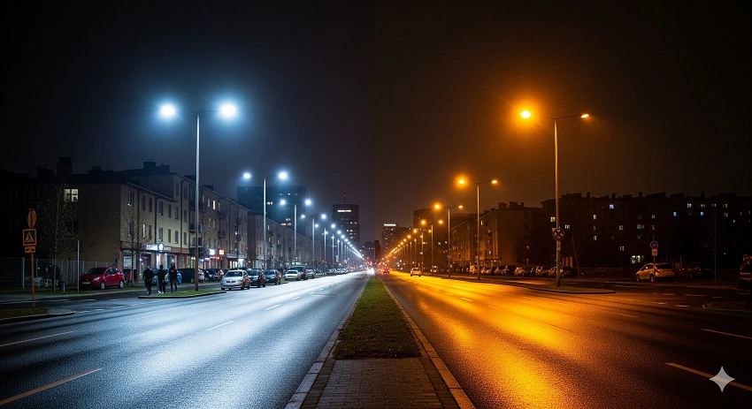
In a parking area, for example, useful light contributes to visibility across traffic lanes, pedestrian areas and other intended surfaces. Light sent above, behind or far beyond those areas does not provide the same project value. Glare can occur when excessive brightness, an unsuitable light direction or strong luminance contrast makes visual details harder to see. Spill light is different again: it may reach adjacent properties, surrounding roads or areas that do not need illumination.
Hot spots and dark zones describe unevenness within the target area. One section may be visibly over-lit while another receives too little light. These conditions explain why flood-light quality cannot be judged from average brightness alone.
Which optical characteristics have the greatest effect on visual comfort and usable light?
The optical characteristics with the greatest effect on visual comfort and usable light include beam distribution, beam angle, optical shielding, fixture aiming, mounting height, fixture position and beam overlap.
Beam distribution determines the shape in which the fixture sends light across the target surface. Beam angle affects how concentrated or spread out that distribution becomes. Shielding or optical cut-off limits direct light in directions where it is not wanted, while aiming determines where the designed distribution actually lands.
Mounting height changes throw distance, beam footprint and viewing angle. Fixture position affects both target coverage and whether a bright source is likely to appear directly in a user’s field of view. Beam overlap then controls the transitions between adjacent fixtures: too little overlap can leave dark zones, while poorly controlled overlap can create unnecessarily bright patches.
Anti-glare performance is therefore a result of optics, mounting, position, aiming and site geometry—not an “anti-glare” label on the luminaire alone.
How do lenses, shielding and aiming work together?
Lenses shape the light distribution, shielding limits unwanted direct light in selected directions, and aiming determines where the designed beam actually lands.
Consider a luminaire installed near the edge of a large outdoor area. The lens may provide the required distribution, but excessive upward aiming can still send light toward observers or beyond the site boundary. A shield can control selected directions, but shielding alone cannot correct a beam that misses the useful target. The three decisions must therefore be treated as one optical system.
Project teams that need to compare different distributions can review OAK LED’s LED Flood Lights after defining the required coverage. The range provides multiple optical options and anti-glare design features, but the final choice should still follow site geometry and lighting calculation rather than a product specification in isolation.
Which beam-angle options are most useful for large outdoor areas?
Narrow, medium and wide beam angles can all be useful for large outdoor areas: narrow beams generally support longer throws, medium beams balance distance and coverage, and wide beams cover broader nearby areas.
The most suitable option depends on mounting height, fixture-to-target distance, target-area geometry, fixture output and the overlap required between neighboring beams. A beam that works well from a tall mast across a long throw may perform poorly when used from a lower position to illuminate a nearby open area.
How do narrow, medium and wide beams differ?
Narrow beams concentrate light for longer throws, medium beams balance throw and coverage, and wide beams spread light across broader nearby areas.
A narrow beam creates a smaller footprint and can help when the target area sits farther from the fixture or when the design needs tighter optical control. Its main risk is coverage: without enough overlap, concentrated beams can create hot spots and leave darker surrounding areas.
A medium beam offers a practical balance between projection distance and coverage. A wide beam creates a larger illuminated footprint and can work well for broad areas close to the mounting position, but at excessive distance it may spread the available output too widely and leave insufficient illuminance on the target. Wide distributions also need careful boundary control where spill light matters.
These categories describe optical behavior rather than fixed application rules. A 15°, 40° or 120° beam should not automatically be assigned to one type of project simply because the angle sounds narrow, medium or wide. Distance, height, output and layout determine what that angle actually does on the ground.
How do mounting height and throw distance affect beam-angle selection?
Higher mounting heights and longer throw distances generally require more concentrated or controlled distributions, while broad areas closer to the fixture can use wider distributions.
Beam angle only becomes meaningful when it is evaluated together with distance. As mounting height or horizontal throw increases, the design may need tighter control to keep sufficient usable light on the far target. Irregular site geometry can require different strategies again because the optical challenge changes across the same site.
| Project Condition | Optical Challenge | Possible Beam Strategy |
| Higher mounting position or longer throw | Maintain useful light over greater distance | Evaluate more concentrated or controlled distributions |
| Large area close to the fixture | Cover a broader footprint without unnecessary intensity | Evaluate wider distributions |
| Irregular site geometry | Coverage distances and boundaries vary | Use project-specific optics and aiming |
| Spill-sensitive boundary | Useful coverage must stop near the site edge | Use controlled distribution, shielding and careful aiming |
Why can one project require more than one beam angle?
One project can require more than one beam angle because near, middle and far target zones need different combinations of throw distance and coverage.
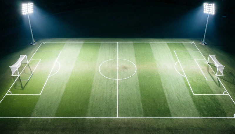
A high-mast installation, for example, may need to illuminate an area close to the pole, a middle zone farther into the site and a far zone near the opposite boundary. Using the same narrow beam everywhere can create concentrated hot spots near the fixture and insufficient general coverage. Using the same wide beam everywhere can waste output close to the pole while leaving distant zones under-lit.
A mixed-beam configuration can solve this by assigning more concentrated distributions to farther targets, medium distributions to intermediate areas and wider distributions to nearby coverage. The correct combination then depends on fixture quantity, beam overlap and aiming.
For general exterior projects, OAK LED’s Outdoor LED Flood Lights provide multiple beam-angle options that can be assessed against the site layout. Where pole height and long-distance projection dominate the design challenge, a High Mast Light configuration can be evaluated with the same project-first logic.
The practical question is not “Which single beam angle is best?” but “Which beam-angle combination produces the required coverage and uniformity from the available mounting positions?”
How can glare, spill light and uniformity be evaluated in an LED Flood Lights design?
Glare should be evaluated from the relevant viewing directions, spill light from illumination falling outside the intended target area, and uniformity from the distribution of light across the complete working surface.
These factors should be checked in the finished lighting layout rather than inferred from the luminaire datasheet alone. The same luminaire can perform very differently when mounting height, aiming or viewer position changes.
How should glare be evaluated?
Glare should be evaluated from the main viewing positions and directions by checking whether high-intensity sources are directly visible and how the fixtures are aimed.
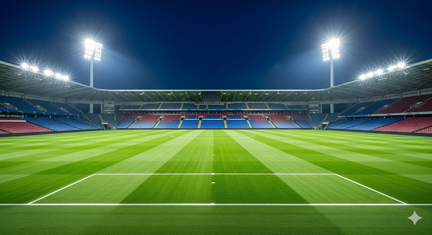
Start with the people using or viewing the area. Identify where they normally stand, move or drive, then examine the directions in which they need to look. In sports or activity areas, consider players and spectators. In high-mast open areas, consider operators or drivers approaching from different directions. In parking and commercial outdoor areas, consider both pedestrians and drivers.
If the source remains directly visible from an important viewing direction, review the aiming angle, shielding, mounting position or optical distribution. The goal is to maintain required target illumination without exposing users to unnecessary high-intensity light.
How should spill light be evaluated?
Spill light should be evaluated by checking how much illumination falls beyond the target boundary, reaches neighboring areas or travels above and behind the intended lighting zone.
This matters for more than neighboring properties. Light outside the useful area consumes energy without contributing to the intended visual task. Reducing it can improve both optical control and project efficiency.
The answer is not always to aim the fixture farther downward. Depending on the geometry, the better solution may involve another beam distribution, a different fixture position, optical shielding or a combination of these changes.
How should uniformity be evaluated?
Uniformity should be evaluated across the complete target surface, including bright zones, dark zones, edges, corners and beam-overlap areas—not from average illuminance alone.
A project can achieve a high average value while still producing uncomfortable or impractical differences between the brightest and darkest areas. Strong hot spots can indicate excessive concentration or overlapping intensity. Darker gaps can indicate insufficient overlap, inappropriate aiming or a distribution that does not match the site geometry.
Uniformity targets themselves should follow the application and applicable project requirements. The design principle is to evaluate how light is distributed across the entire required area rather than treating average lux as proof that the layout works.
Why should photometric simulation be used before final fixture selection?
Photometric simulation should be used because it shows how the selected fixtures, optics and aiming will perform on the actual site before equipment is ordered.
- Collect the site dimensions and target lighting areas.
- Confirm mounting positions and mounting heights.
- Define the required illuminance, uniformity and boundary conditions where available.
- Select preliminary fixtures and beam distributions.
- Run the photometric model with the proposed positions and aiming.
- Check illuminance, uniformity, glare-sensitive viewing directions and spill-light boundaries.
- Adjust fixture quantity, output, optics and aiming.
- Confirm the final optical configuration before ordering or installation.
This is where OAK LED’s lighting-design, manufacturing and customization capabilities become relevant. Instead of forcing one standard beam configuration into every project, wattage, beam angle, fixture quantity, aiming and fixture configuration can be reviewed together before the final lighting proposal is confirmed.
Typical priorities also change by application. High-mast open areas often combine long throw, different target distances, glare and beam-overlap challenges. Sports and activity areas add player or spectator glare, uniformity and spill-light control. Parking and commercial outdoor areas often place more emphasis on dark-zone control, pedestrian visibility, edge coverage and keeping unnecessary light beyond the site boundary.
What Project Information Is Needed Before Selecting Flood-Light Optics?
Before selecting flood-light optics, provide the site drawing, dimensions, mounting positions and heights, throw distances, target areas, lighting targets, spill-sensitive boundaries and main viewing directions.
- Site drawing and overall dimensions
- Application and target lighting areas
- Existing or planned fixture positions
- Mounting height
- Horizontal throw distance to important target zones
- Existing fixtures for retrofit projects
- Required illuminance, if specified
- Uniformity target, if specified
- Boundaries or areas where spill light must be controlled
- Main viewing, operating or traffic directions
- Environmental conditions
- Dimming or control requirements
Providing this information lets the optical selection start from the project rather than from a preferred beam-angle number. It also gives the design team enough context to test whether one distribution is sufficient or whether a mixed-beam configuration will perform better.
Send your site layout, mounting height, throw distance and target lighting requirements to OAK LED to discuss a project-specific flood-light optical layout.
FAQ
Can existing flood-light mounting positions be kept when changing the optics?
Possibly, but the existing positions should be rechecked against the new beam distribution, aiming and target coverage.
Changing the optics changes the beam footprint, so mounting height, pole location, aiming and beam overlap may produce a different result even when the fixtures remain in the same positions. A lighting layout should verify the revised configuration before installation.
Does changing the beam angle require changing the fixture wattage?
Not necessarily. Changing the beam angle primarily changes light distribution, but that change can also affect illuminance, coverage and uniformity on the target area.
The project may therefore need to re-evaluate fixture output, quantity or aiming. A narrow beam does not automatically require higher wattage, just as a wide beam does not automatically require lower wattage.
Effective LED flood-light optical design balances usable light, visual comfort, beam coverage, glare control, spill-light control and uniformity. None of these depends on optics alone; mounting height, fixture position, aiming and project geometry determine how the optical system performs on site.
The next step is to verify those factors together in a photometric layout. Once the project team can see where the light lands—and where it does not—the final beam distribution, fixture quantity, output and aiming can be selected with much greater confidence.