Buyers should compare COB and SMD LED flood lights by the performance of the complete luminaire, the lighting each proposed installation delivers, and the cost of achieving the same project requirements. Start with measured input power, luminaire lumens, photometric distribution and thermal design. Then model the candidate fixtures on the actual site before comparing installation, energy and maintenance costs. The packaging technology is an engineering choice, not a verdict on which product is better.
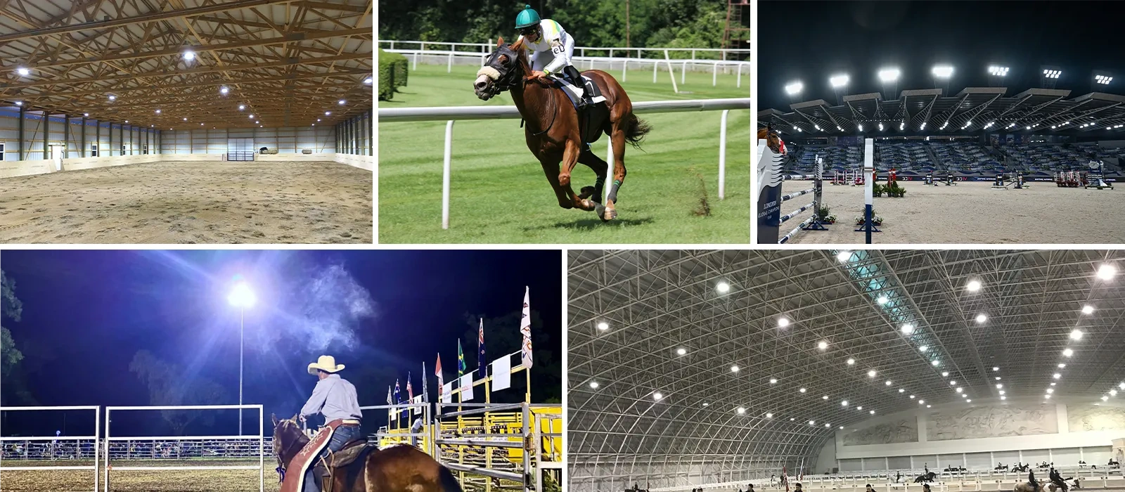
Imagine a contractor replacing high-powered floodlights around a sports ground. One supplier recommends a compact COB fixture; another proposes a modular SMD system. Both brochures advertise strong output. What the contractor still needs to know is whether either proposal lights the far boundary, controls glare toward nearby properties and remains serviceable on a high mast. Those questions establish a useful comparison far more quickly than a generic list of COB and SMD advantages.
COB and SMD Create Different Design Options
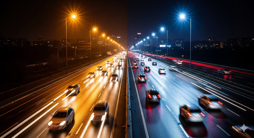
COB and SMD describe how the LED light sources are packaged and arranged. In a chip-on-board (COB) assembly, multiple LED dies share a compact emitting structure. A surface-mounted device (SMD) design uses individually packaged LEDs, usually arranged across one or more circuit boards or modules. These differences influence the size and geometry of the emitting area, and they give luminaire designers different ways to arrange reflectors, lenses and heat paths.
A compact COB source can help shape a concentrated beam with matched optics. That does not make every COB floodlight a long-throw product. The reflector or lens, source dimensions, operating current and mechanical arrangement still determine the actual intensity distribution. A poorly matched optic can waste the advantage of a compact source just as easily as a well-designed one can use it.
SMD packages can be distributed across modules, with individual or shared secondary optics directing light into different parts of a scene. The layout gives the manufacturer flexibility in building modular or asymmetric distributions, but it does not guarantee a wide beam, better efficiency or more uniform illumination. A tightly controlled SMD high-mast fixture can deliver focused light, while another SMD product may be intended for wide-area coverage.
Both approaches place demands on the heat sink, housing, driver and sealing system. How heat moves out of an LED module matters more to its operating conditions than the package label on a quotation. For a buyer, the practical value of knowing the source technology is to ask better questions about the proposed optics, module construction and maintenance access. The next step is to examine the finished fixture rather than continue comparing package diagrams.
Compare the Light the Finished Fixture Can Deliver
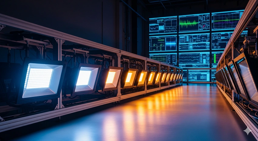
A defensible technical shortlist begins with complete-luminaire data measured under comparable conditions. Wattage establishes electrical demand; lumens establish total emitted light; lumens per watt connect the two. None of those three figures alone establishes whether a sports field, loading yard or parking area will receive useful illumination at the required positions.
For example, two floodlights with the same total lumens may put very different amounts of light near the foot of a mast and at the far edge of the target. The difference appears in the luminous intensity distribution, normally expressed in candelas by direction. A nominal 30-degree beam angle is not a substitute for the full distribution, especially where aiming, shielding and oblique mounting change the footprint.
| Comparison measure | Evidence to examine | Project decision it supports |
| Complete-fixture input power (W) | Measured system power, including the driver | Electrical loading and later energy calculations |
| Luminaire lumens and efficacy (lm; lm/W) | Measured output and efficacy under identified conditions | Shortlisting output and efficiency without using LED-chip claims |
| Intensity distribution (cd) | IES or LDT file for the actual optical configuration | Aiming, throw distance, coverage and light outside the target |
| Project lighting results | Calculated minimum and average illuminance, applicable uniformity and glare measures | Whether the proposed installation meets the lighting brief |
| Operating compatibility | Ambient rating, color characteristics, dimming and control interface | Suitability for the site and its electrical system |
Usable Coverage Matters More Than a Headline Lumen Figure
Lighting performance becomes meaningful when the project defines its target surfaces and acceptable results. On a playing field, the far corners and areas seen by players or cameras can matter as much as the average value. In a loading yard, drivers and pedestrians need to see changing obstacles without discomfort from exposed light sources. A high-lumen fixture that creates a bright patch directly below the pole may require a different optic or a revised aiming pattern to serve those areas.
That is why a photometric file is more useful than a stand-alone beam-angle claim. The file lets an engineer model light distribution from the proposed mounting positions and evaluate both useful coverage and unwanted spill. Shielding, aiming and neighboring luminaires further influence the result. OAK LED’s LED flood light optics selection guide examines those optical decisions in greater detail; the COB/SMD buying comparison should focus on the effect of the chosen optics on the complete proposal.
Thermal Design and Serviceability Set the Operating Margin
Reliable floodlighting depends on the assembled system staying within suitable electrical and thermal conditions. Inspect the heat-sink path, driver specification, rated ambient temperature and any stated reduction in output at higher temperatures. A high-mast luminaire installed in strong sun or a hot industrial setting may face more demanding conditions than a similar fixture used for an evening-only commercial site. Its published ambient rating needs to be understood alongside the manufacturer’s operating and testing assumptions.
Service access also changes the reliability discussion. Can a driver or module be replaced separately? Will maintenance require removal of the entire fitting from a mast? Are seals and mounting components designed for the site’s exposure? These questions affect downtime and repair cost regardless of whether the LEDs are COB or SMD.
LED-source lumen-maintenance data should not be confused with proof of a complete fixture’s service life. LM-80 measurements and TM-21 projections address LED components, while the finished product also depends on its driver, optics, connections and other parts. The Illuminating Engineering Society’s position on LED product lifetime specifically identifies this distinction. Warranty terms, replaceable parts and the specified environmental rating therefore remain part of the engineering evaluation.
Let the Site Determine the Optical Configuration
Once the shortlist has credible fixture data, the installation geometry determines which configurations are worth modelling. Mounting height, distance to the target, available aiming angles and nearby properties can change the value of a particular beam distribution. The same luminaire may suit one outdoor space and underperform in another.
Return to the sports-ground replacement. The highest-priority areas may sit a considerable distance from existing masts, while the nearest houses limit acceptable spill light. The designer may combine different distributions across the same mast rather than use identical optics in every position. A COB proposal and an SMD proposal can each be valid, provided the selected models deliver the required throw, uniformity and glare control. Airport apron lighting also requires site-specific analysis and is distinct from regulated runway or taxiway lighting.
Now consider a car park and adjacent loading yard. Lighting needs change near entrances, pedestrian paths, reversing areas and property boundaries. The strongest design may use broader coverage in an open zone and more controlled aiming beside a neighboring building. The total number of poles and fixtures, ease of access and operating hours can influence which layout is practical. Neither a COB package nor an SMD array automatically dictates the coverage strategy.
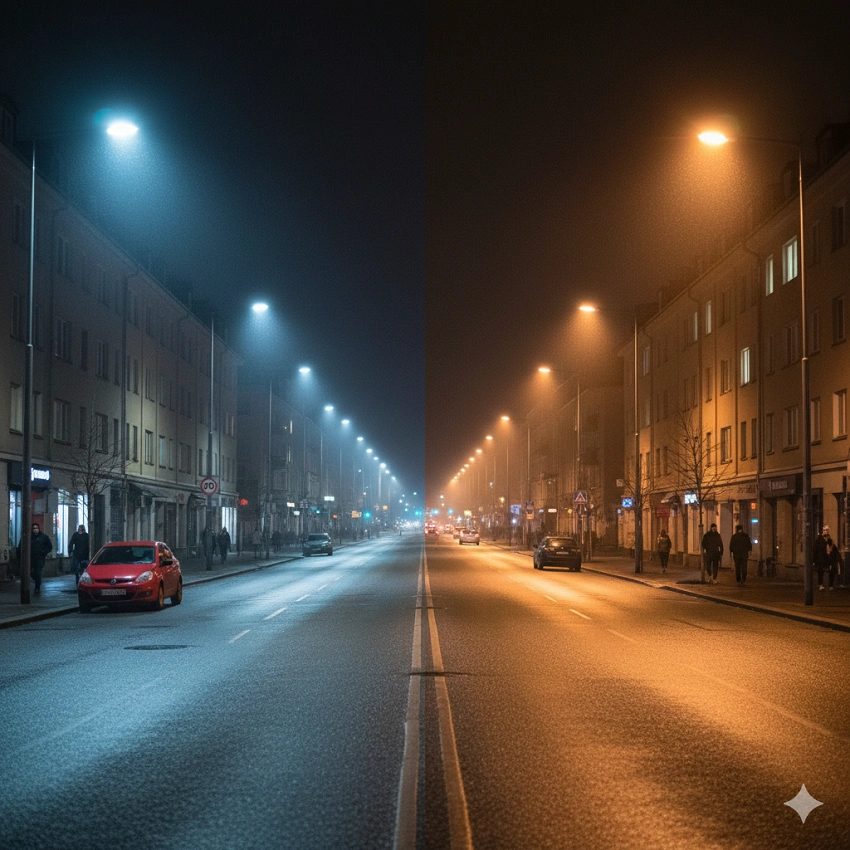
Facade lighting creates a different challenge. A narrow accent on an architectural feature demands precise aiming and restraint; a broad wall wash needs coverage that avoids distracting hot spots. Color quality, consistency and dimming may be central to the brief. Where RGBW effects or networked controls are required, the actual driver and control system must support them. The package name does not tell a buyer whether those functions exist.
Environmental requirements can narrow the selection before optical modelling begins. Coastal installations need appropriate corrosion protection; hot process areas need evidence for the specified operating temperature; hazardous locations require products approved for the applicable area classification. These are application requirements, not inherent COB or SMD properties.
For a practical product shortlist, our COB LED floodlight configurations and SMD high-mast floodlight configurations provide different design starting points. The site brief, exact model and optical files decide which products proceed. A family-page specification is not a substitute for comparing the configurations actually quoted.
Turn Product Data into an Auditable Lighting Proposal
The next stage is evidence, not another debate about the LED package. A credible proposal must connect a particular fixture and optic to its test documents and then show how that fixture performs in the intended installation. Keeping these two checks separate prevents a good product test from being mistaken for proof that a field layout will work.
Match Reports to the Quoted Configuration
Ask for model-specific electrical and photometric measurements, matching IES/LDT distribution files, applicable environmental and safety information, relevant lumen-maintenance evidence, installation drawings and warranty terms. ANSI/IES LM-79-24 sets out methods for measuring solid-state lighting products’ optical and electrical characteristics under defined conditions. It supports comparison of tested luminaires, provided the documents correspond to what will be supplied.
Check the model code against the quotation, especially the optic, driver and color configuration. A laboratory report for one variant may not establish the performance of a different beam, power setting or driver. If those details change, the supplier should identify the applicable evidence. This simple document check can prevent a design based on one fixture from becoming a purchase of another.
Evaluate Competing Layouts Against the Same Brief
For the site comparison, keep geometry and acceptance requirements consistent, while allowing each proposal to use the optics and fixture positions best suited to the job. An SMD system may use several modular units where a COB system uses fewer higher-output fixtures, or the reverse. Forcing both to have the same wattage, beam angle or unit count is not a fair test of which design meets the brief.
Use the actual mounting positions and permitted aiming angles in a lighting model. For each scheme, the review should record:
- Maintained average and minimum illuminance at the agreed target surfaces.
- Applicable uniformity, glare and spill-light results, including sensitive site boundaries.
- Fixture number, mounting and aiming details, and total connected input power.
- The exact model, driver, optic and control settings on which the calculations depend.
These records create a clear technical decision. A layout that misses a required minimum should be corrected or excluded rather than rescued by a low unit price. Where aiming or optics are revised, the calculation should be updated before approval. The contractor then has a documented design against which substitutions and commissioning observations can be checked.
With those design results available, procurement can move from two competing brochures to two identifiable installations. The difference matters most when an adjustment to one mast, beam pattern or fixture quantity changes the project budget.
Compare the Installed Project Cost, Not the Fixture Price
Only technically acceptable proposals should enter the final commercial comparison. At that point, the relevant price is the cost of the complete system delivering the specified light, not the price of a single floodlight. The fixture count affects equipment and labour, while positioning, cable routes, control zones and access arrangements shape the rest of the budget.
A lower-power luminaire is not necessarily the lower-energy choice for a site. If the layout requires more fittings, the total installed input power could be higher. A cheaper fixture could likewise lead to more brackets, extra circuits or higher future maintenance access costs. This is particularly important on high masts, where reaching a driver or lifting a luminaire can disrupt operations.
Compare both systems over the same chosen evaluation period. A practical total-cost calculation combines equipment, installation, electricity, planned maintenance and expected replacement work, with the same tariff and operating assumptions for each scheme. Annual energy use begins with total connected power in kilowatts multiplied by operating hours. If occupancy controls or dimming schedules change power over time, calculate those periods separately using appropriate power values.
Consider what a small difference in fixture quantity means to installation. One proposal may need fewer high-output luminaires but more substantial mounting hardware; another may need more electrical connections yet place smaller modules where technicians can reach them. Neither scenario wins on the drawing alone. The supplier’s schedule and contractor’s installation estimate need to describe the same approved design before the figures are comparable.
Approve the lighting performance first; compare lifecycle cost between the designs that actually meet the site requirements.
Before purchase, tie every quotation to the fixture schedule, specified optics and drivers, accessories, controls, delivery terms and warranty coverage. Spare drivers and modules also deserve a place in the discussion. This turns the cost review into a practical purchasing decision rather than a misleading contest between two list prices.
Two Installation Details That Deserve a Final Check
Once a design has passed its optical and commercial review, two practical questions can still affect the installation schedule.
Can COB and SMD Floodlights Be Used in the Same Project?
Yes. COB and SMD floodlights can operate in the same project if the complete mixed layout meets the required lighting performance and their electrical, color and control arrangements are compatible. Evaluate the combined installation rather than assuming that individually suitable products automatically work together.
Can Existing Brackets Support a Replacement SMD Floodlight?
Sometimes. Existing brackets or poles may remain in use when the new fitting meets the relevant connection, weight, wind-load and electrical requirements. Its new beam distribution and aiming still need assessment, even if the mounting hardware itself does not change.
Bring the Project Brief to a Side-by-Side Review
Send OAK LED the target-area drawing, mounting heights and positions, required illuminance, operating conditions, and glare or spill-light limits for a free project lighting assessment. For a retrofit, include the current fixture schedule and any restrictions on existing poles, brackets or wiring. Those inputs allow our team to develop suitable COB and SMD luminaire configurations and prepare a meaningful lighting layout, with manufacturing and OEM/ODM support where required.
Request the proposed fixture schedule, model-specific photometric files and lighting calculations before approving the order. These documents support performance checks and comparable project costing. Formal acceptance and site verification still follow the applicable project requirements.